 |
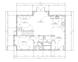
| A simple floor plan with dimensions. Remember, though, that there are many different types of plan drawings. |
The good news is that architectural drawings are not that mysterious. If you can live with the concept of using two dimensions to represent three, the rest is easy. There are only three basic types of architectural drawings:
• The first type is called a plan. A plan is any view looking straight downward. The best-known of these is the floor plan, which cuts an imaginary horizontal slice through a house in order to show walls, doors, and the like. But there are many other kinds of plans. For example, a site plan shows the property that the house will be built on; a foundation plan shows the concrete foundation; an electrical plan shows the location of lighting fixtures, switches, and receptacles; and a roof plan shows the roof surfaces and how they intersect.
 |
| Elevations: Front, right, rear, and left, though in this case, they're labeled by compass direction. |
There are two other types of elevation: An interior elevation is used to show interior features like fireplaces or archways, or other features that can’t be fully described in a plan alone. For example, the floor plan may show an arch, but what kind of arch? Round, square, elliptical, segmental, Moorish? The interior elevation helps clarify such features.
Finally, a cabinet elevation (also called a casework elevation) shows the cabinetwork as seen from the front. While a kitchen floor plan can show the basic location of cabinets and counters, a cabinet elevation is needed to show the exact size and location of cabinet doors, drawers, shelves, and the like. It’s typically drawn for kitchens, bathrooms, and any other complicated interior areas.
 |
| A simple section drawing. In this example, it's fairly easy to recognize that it's a slice through the building. |
For most people, sections are the most difficult drawings to read. Unlike plans and elevations, they don’t always look like a recognizable part of a house. But once you get used to the concept of cutting slices through the house to see what it’s made of, you’ll find yourself reading them like a pro.
• Finally, any one of these three drawing types can be used to zoom in on a particular aspect of the building to show it more clearly. The resulting larger-scale drawing is called a detail. For example, an unusually-shaped rain gutter may be too small to distinguish on a section, so the architect draws an enlarged version of the gutter to describe it more clearly.
No comments:
Post a Comment